Building an LED Matrix Driver
I’m lucky to have friends working in the electronics industry in various different capacities. Through them, I’ll occasionally get hold of some unwanted/rejected/surplus boards or components that would otherwise just end up in the WEEE bin. It’s always nice when one of these lands on my desk that I think “hey! I could do something with this!”. Recycling!
The Boards
This time, it’s some LED boards. Each board has 100 LEDs pre-soldered to it. There’s no connection between any of the LEDs, but they are arranged into a 20-by-5 matrix. There are M3 and M2.5 holes drilled at the top and bottom of each LED. The boards measure ~145mm by ~240mm.
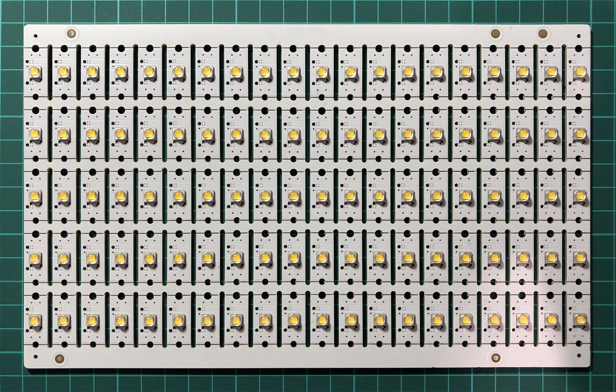
These boards aren’t intended to be used as-is, they’re break-outs for individually-mounted LEDs that are used for a high-output illumination application in a product. The actual LEDs used are Cree® XLamp® XM-L type, which are insanely high-output chips with a maximum DC forward current of 3 amps - at that current though they require significant thermal management and are unpractically (and eye-damage-inducingly) bright for most applications.
I decided that at a more sensible current, the rectangular array layout of the LEDs could be leveraged to produce a display. I set to work finding a suitable driver to run the whole array as a multiplexed matrix.
Driver Shopping
I know nothing about LED drivers; and sometimes, coming to a completely new field like this, you often don’t even know what to Google to find what you’re looking for.
Search terms like “led matrix driver ic” and “led array driver” were annoyingly good at finding offerings from ST and other companies that were mainly focussed on driving large LED backlight panels (controlling many LEDs in the same way at the same time). That seems to be a far more common requirement these days with the prevalence of LED backlights for large LCDs. My requirement was for an LED multiplexer IC that could individually modulate the output of LEDs in an X-Y matrix.
Eventually though, you start to stumble on terms that are more conducive, or rule out unwanted offerings with boolean searching (-backlight etc). TI’s TLC5958 looked like a good prospect - 48 channels, PWM modulation multiplexing. A few downsides irked me though - the requirement for the LED common anodes to be switched using your own external FETs for instance.
Eventually, I found a more straightforward option from ISSI (Integrated Silicon Solution Inc.). Their IS32FL3738 (6x8 Dot Matrix LED Driver) looked like it ticked all the boxes - all switching on both the anode and cathode side taken care of; easy to communicate with via I2C; a straightforward-to-solder TSSOP package. The chip has 8 current sources and 6 current sinks, so that would mean I would need 3 of them to control the entire panel (with some spare/wasted capacity given the odd number of LEDs on the board - 100).
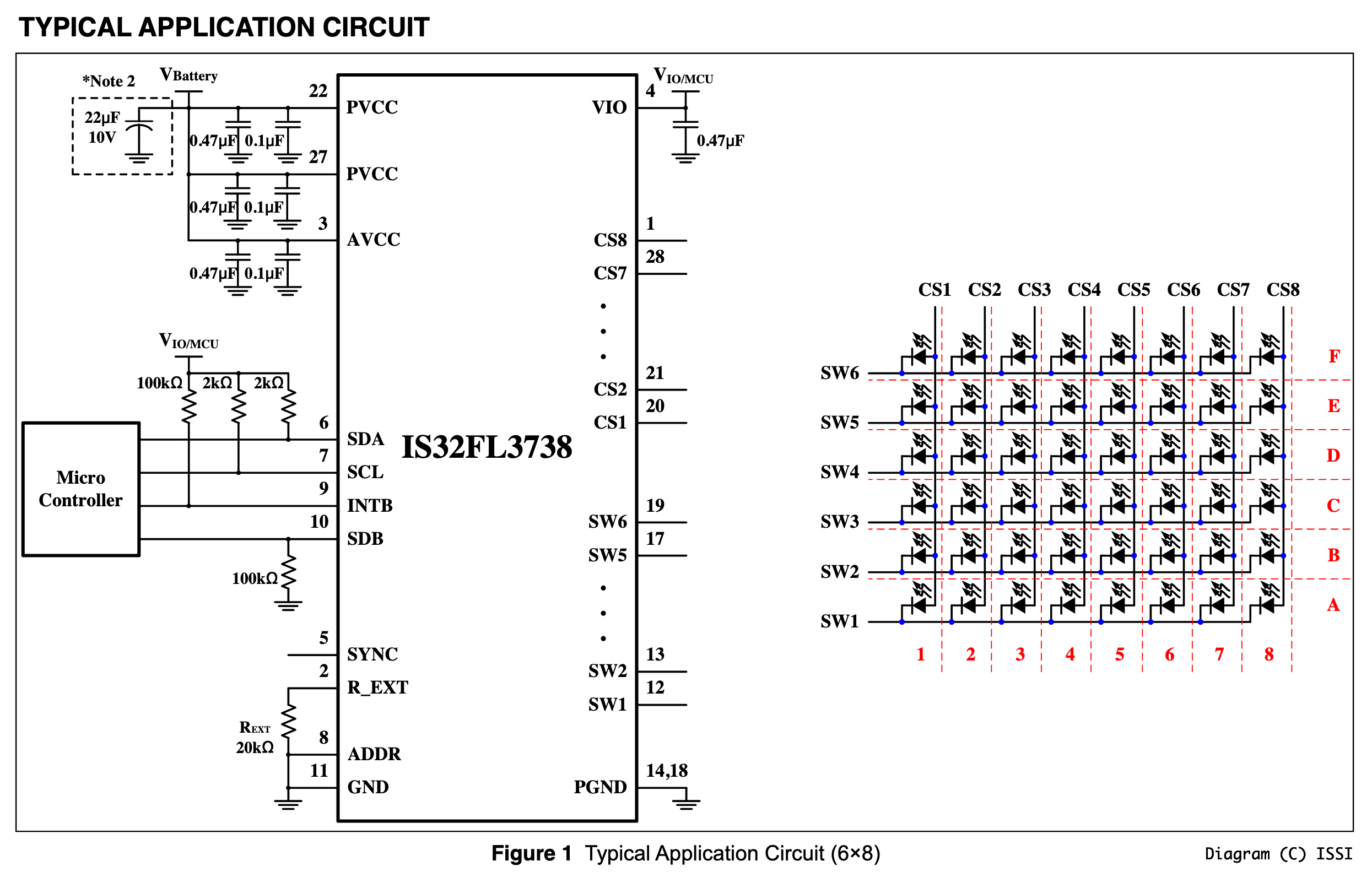
The SYNC output of the chip also allows daisy-chaining of a number of chips that will keep PWM synchronisation with one another to avoid any “rippling” effects across a larger display.
Designing a Controller
The main features for the controller I had in mind included:
- Wi-Fi connectivity for displaying push notifications, synchronising with an NTP time server.
- 5V power input, either via Micro-USB or a DC barrel connector.
Like almost everything I make, I decided to base the controller around my favourite microcontroller architecture - Espressif Systems’ ESP32 RF SoC. In this case, for speed of development and assembly, I went for the ESP32-WROOM castellated SiP with the 4MB SPI flash integrated inside too.
I started schematic work - initially on paper, then in KiCad EDA. I’ve used ESP32 in plenty of designs previously, so my general system design for the microcontroller/power supply/USB aspects of the system could largely be copied and pasted from previous projects. This is always a great way to avoid errors in your designs if you can!
Notable additions included a DC barrel connector, diode-OR’d into the 5V USB power rail with two 3A schottky diodes and appropriate fuses; a Silicon Labs CP2102N USB-to-UART Bridge controller IC to allow communication with the ESP32 SiP via USB and a pair of momentary push-buttons to allow limited user input.
Layout
The physical shape of the controller board made sense to in some way mirror the form-factor of the LED boards themselves, so I made my initial PCB shape 145mm high (the same as the LED boards) and 22mm wide (to cover two of the columns of the LED board with a position for fastening it with M2.5 machine screws, and just wide enough for the ESP32 SiP).
The layout of the actual controller ICs was the most important aspect, and also the most challenging. Breaking out the 14 outputs while also ensuring good power & ground connectivity was tricky. I found that using the front copper layer for the current sinks and the rear copper layer for the current sources worked well. Routing the I2C communication traces on the back of the board allowed me to keep them together and also keep space around the ICs for the much-needed decoupling capacitors for these power-hungry chips.
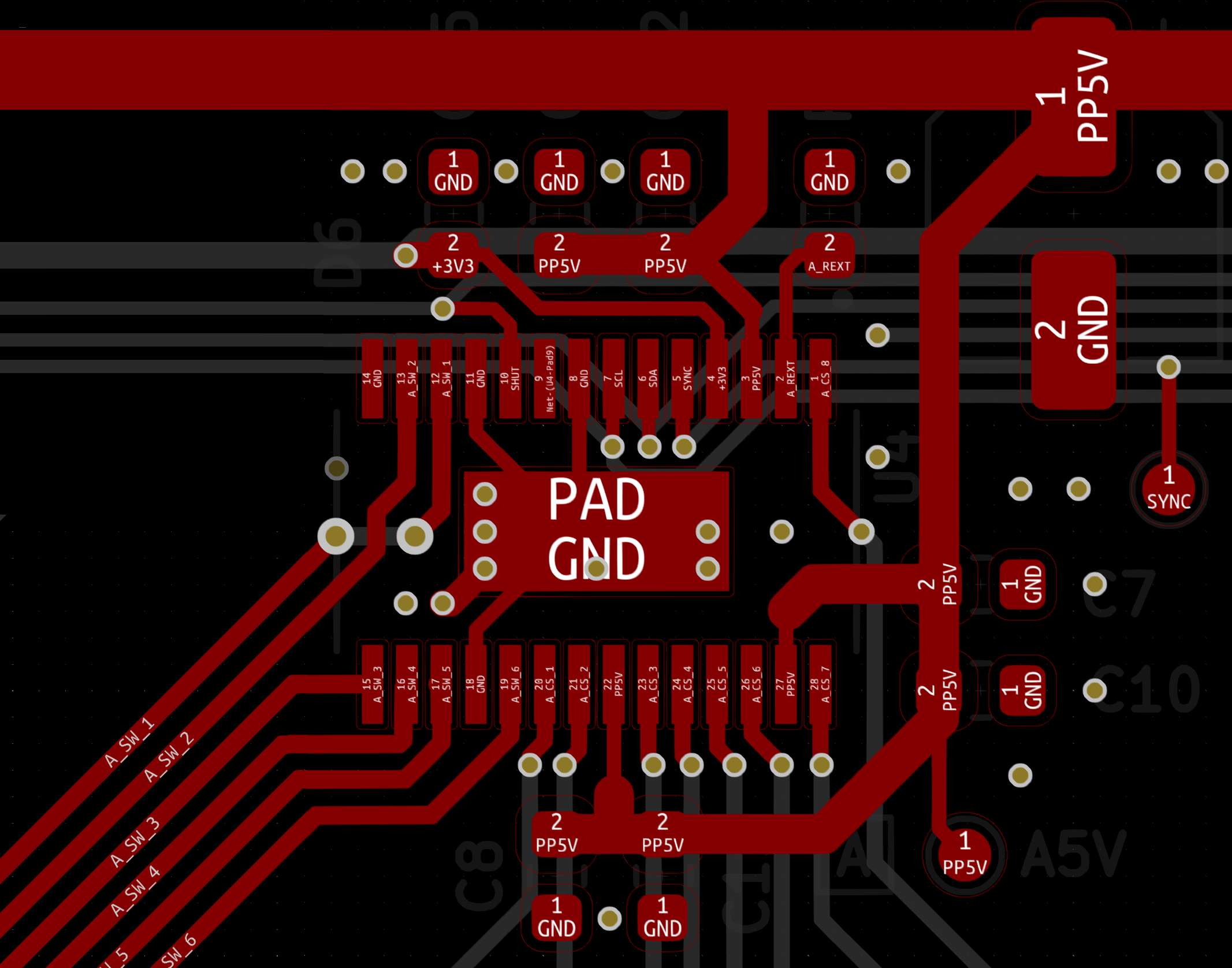
For the LED driver outputs, I just went with a pair of 8-way/6-way right-angle 0.1” DuPont/Professional Pin connectors (J2-J7) for each controller IC, as these are flexible for future use too.
I ended up having to increase the width of the PCB to 27mm in order to accommodate the push-switches at the edge (SW1 & SW2), as well as a heartbeat LED (D4) (I always like to have some visual indication output capability on my designs, even if it’s just a single LED to let you know the power is on!)
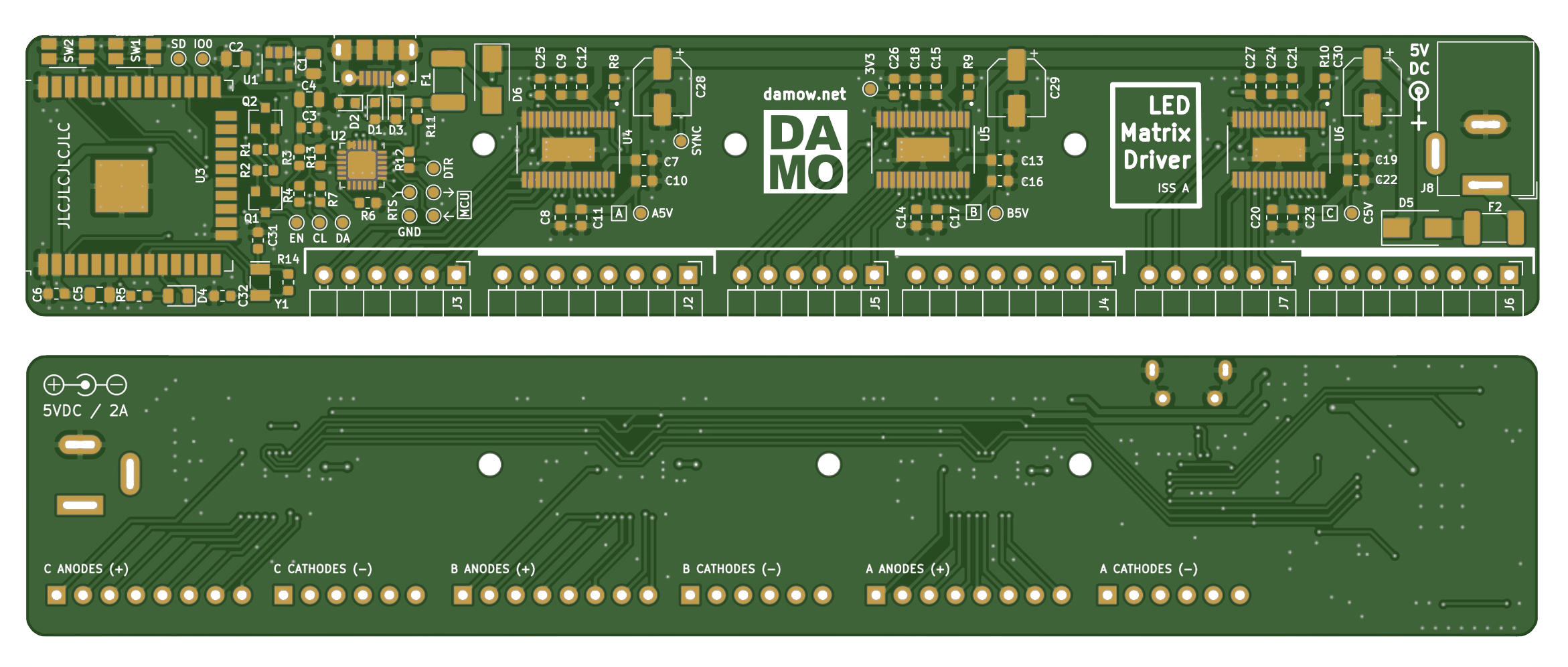
For the mounting of the PCBs to the LED boards, I opted to use the routed slots (which can accommodate M2 machine screws) rather than the drilled holes since this would be more forgiving and offer more flexibility in future.
Once I was happy with the layout, I sent it off to JLCPCB in China to be manufactured! I also ordered all the parts on the BOM that I’d need to assemble the working controllers.
You can check out all the PCB CAD/CAM files for the project on GitHub.
Preparing the LED Boards
While I was waiting for the PCBs to be finished, I addressed a slight problem presented by the LED boards - there was absolutely no connectivity between the LEDs. The IS32FL3738 ICs have 8 source outputs and 6 drain outputs each, therefore I needed the LED anodes to be commoned together in groups of 8 columns with the cathodes commoned together in rows within the groups.
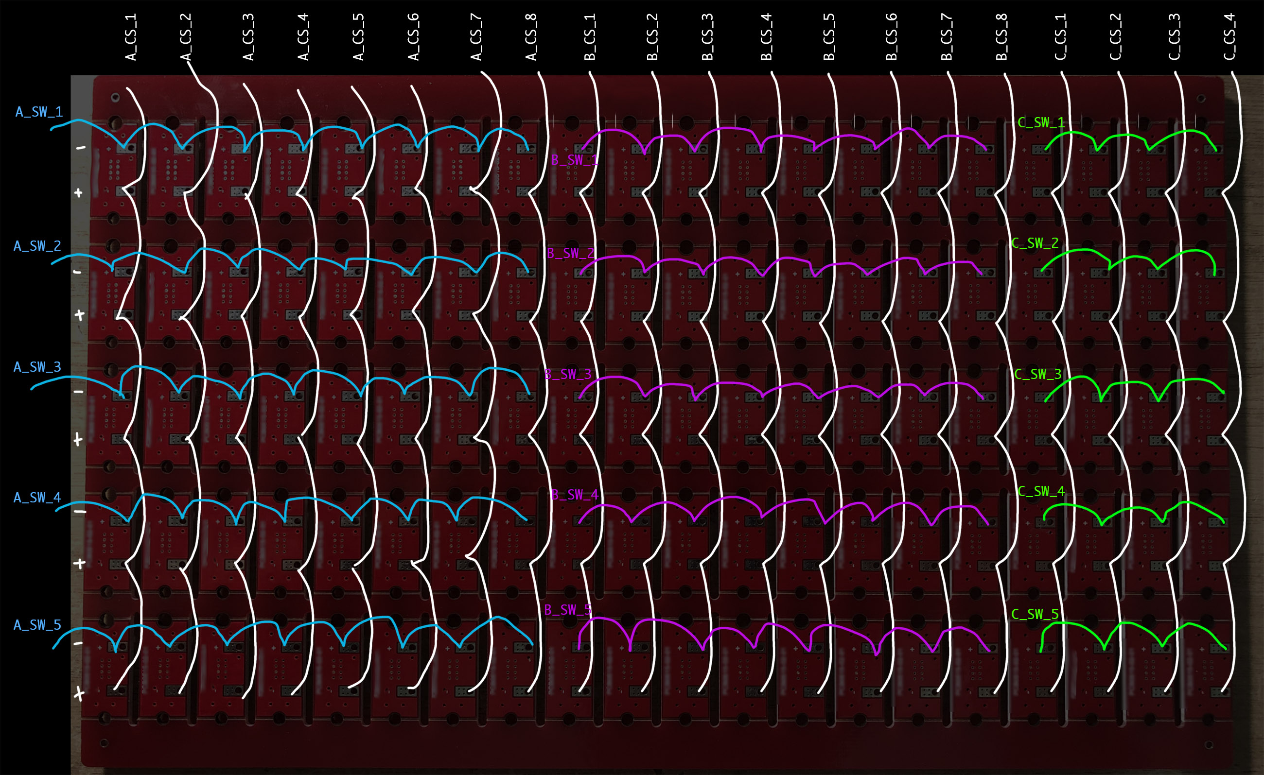
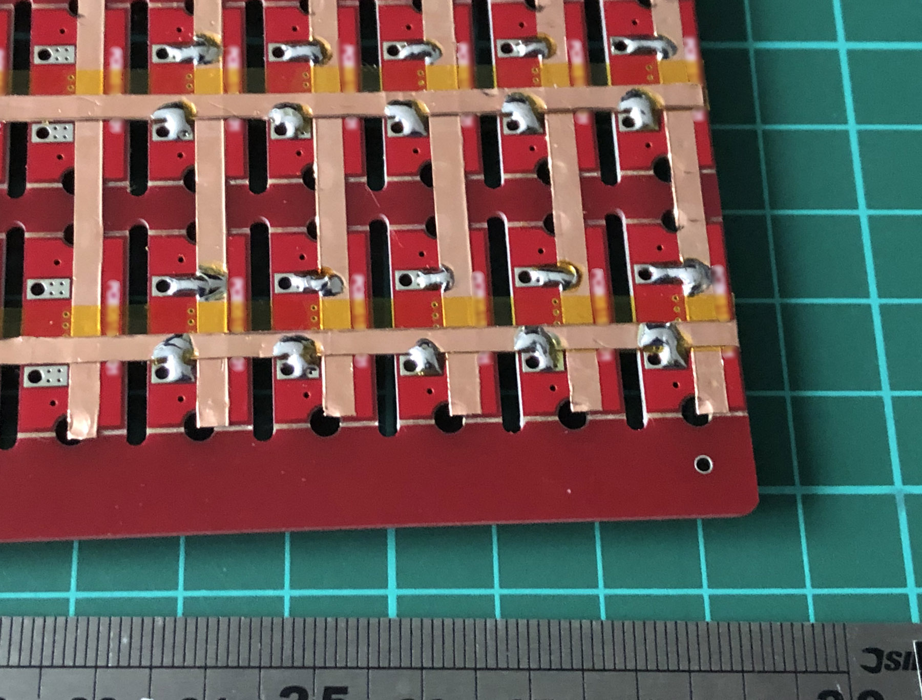
I experimented with different wiring approaches but the best approach by far proved to involve self-adhesive copper tape applied in strips across the PCB and then solder-bridged to the required contacts. For any places where the tape strips needed to cross, I used Kapton polyimide tape to provide some insulation between the strips. This was all very fiddly at first but after a while I became quite efficient at cutting the 3mm-wide strips of copper tape and applying them accurately. I’d always recommend the use of fume extraction for soldering, but particularly so when soldering to copper tape as the lacquer coating produces a lot of nasty smoke during soldering.
Once I’d completed the wiring, I soldered on some ribbon cables and crimped 5-way/8-way DuPont connectors onto them to connect to the driver board. This is probably the aspect of the build that I’m least-pleased with - I just couldn’t find a way to neatly organise the cabling while keeping it long enough to allow easy development with both the LED board and controller board facing upwards.
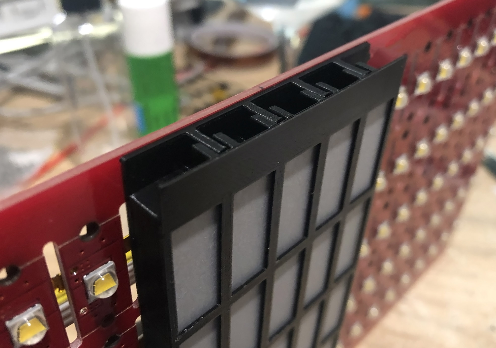
In parallel with this, I also set a series of 3D prints into production - a diffuser assembly I designed (actually a suggestion from my dad!) to make the bright points of the LED chips more usable as a display. These just sandwich a piece of standard tracing paper between the framework in order to turn the tiny bright LED points into diffuse rectangles.
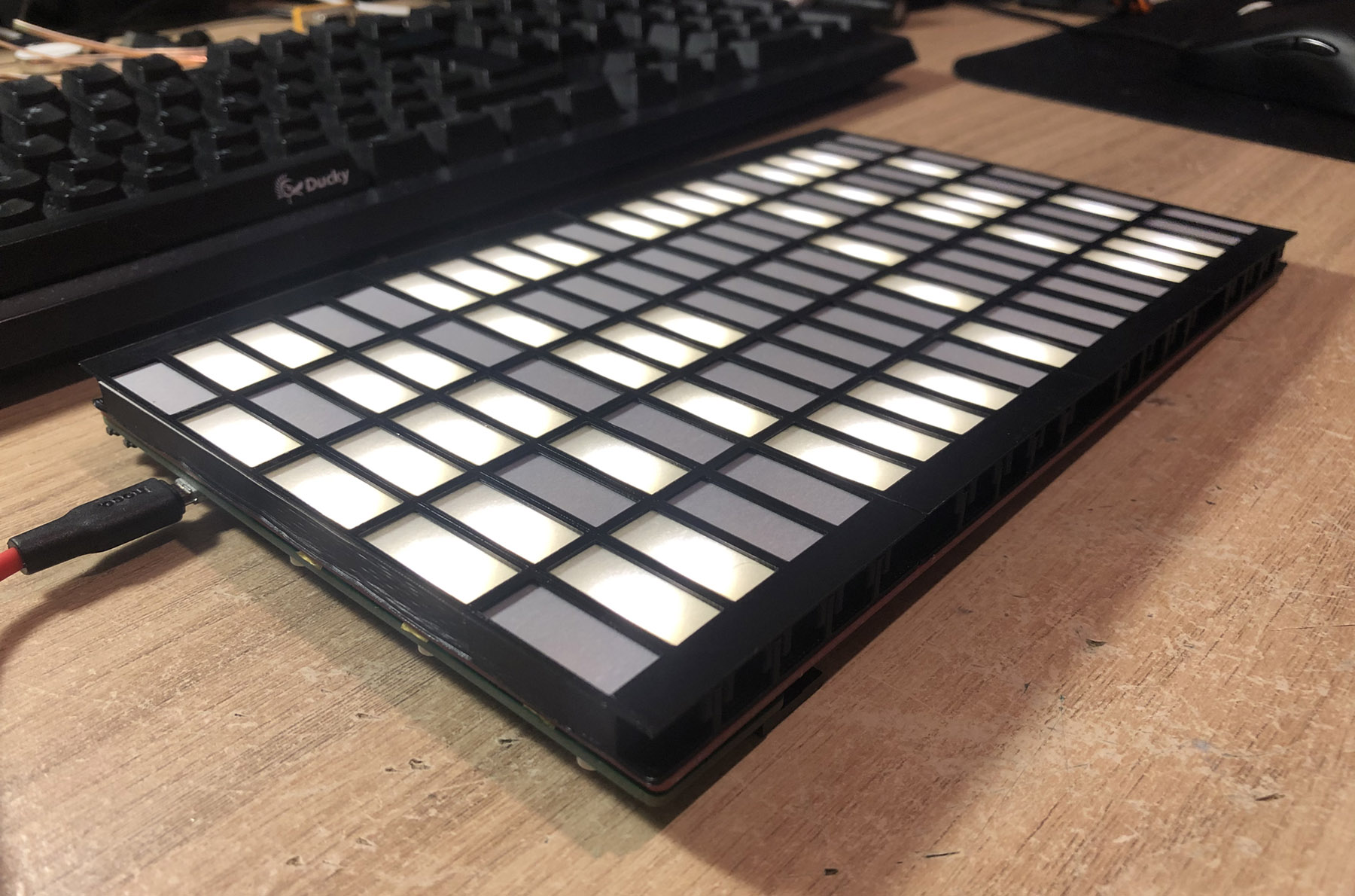
Eventually, the PCBs arrived and I was able to assemble a working controller! With REXT fitted as 20k and the Global Current Control Register (GCR) of the three IS32FL3738s set to the maximum value (0xff) and all LEDs running at maximum PWM duty & current (0xffffffff) the panel draws about 1.3A (~13mA per LED). Even at this very low current, the LEDs are insanely bright. I can’t see any requirement to run the LEDs at higher power than this for any display application.
Programming
Writing the firmware to drive the IS32FL3738 controller ICs was fairly straightforward. I ended up implementing (or rather re-using) my own bit-banged I2C driver because the ESP-IDF one always felt slightly overcomplicated for most applications.
I split the functionality into three layers - the I2C driver (i2c.c) (that just deals with generic I2C communications), the IS32 driver (is32.c) (that deals with the page/register arrangement and any statefulness of the IS32 ICs) and the display driver (display.c) that deals with mapping a logical arrangement of pixels in memory to the actual display geometry. This final layer exposes a nice API for filling, drawing and rendering text onto the display - all with control over the PWM-set brightness of each LED pixel.
As always, you can check out the code I wrote for the project on GitHub.
Overall I was really happy with how the design came out. Given that it looks like a lot of our time will be spent indoors over the next few months, I think I might build the rest of the boards up and assemble some sort of large banner type display with the individual controllers connected via Wi-Fi and controllable as a single unit. That’s a lot of copper tape to cut…
Stay safe & happy hacking!